Magnetic Effects of Electric Current - Class 10th Science
Solenoid
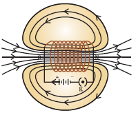
Magnetic Field due a Current in a Solenoid
A coil wound into tightly packed helix is called a SOLENOID, in general. In physics a SOLENOID can be defined as a long and thin loop of wire usually wound around a metallic core.
When electric current is made to flow through the wire, a solenoid gives uniform magnetic field in a volume of space. Thus, a SOLENOID can be used to make an electromagnet.
- Magnetic field produced by the current carrying solenoid is similar to a current carrying conductor.
- Magnetic field lines near the periphery of the loops are arranged in concentric circles.
- Magnetic field lines towards the centre of the loops are arranged in the form of straight lines.
- One end of the solenoid behaves like the North Pole, and another end behaves like the south pole of the electromagnet.
- The direction towards which the straight magnetic field lines appear to be going is the North Pole, while its opposite end is the south pole of the electromagnet thus formed.
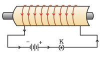
Since number of turns of wire multiplies the electric current and thus magnetic field, therefore, large number of turns of wire in the solenoid, is add on effect and the magnetic field. Thus solenoid produces very strong magnetic field.
Since, magnetic field lines are straight through the centre of the solenoid’s lumen; so there is uniform magnetic field inside the solenoid. If a soft iron bar is placed inside the solenoid; it would turn into an electromagnet.
The strength of magnetic field produced by a current –carrying solenoid depends on following factors:
- Number of turns in solenoid: More number of turns means greater magnetic field.
- Strength of current in solenoid: Strength of magnetic field varies directly as the strength of electric current flowing through the solenoid.
- Nature of 'core material' in solenoid: Soft iron; used as a core; produces the strongest electromagnet.
Force on a Current Carrying Conductor in a Magnetic Field
A current carrying conductor produces magnetic field which exert a force when a magnet placed near the current carrying conductor. Just opposite to it, a magnet exerts a force if a current carrying conductor is placed near it.
It was Andre Marie Ampere, a French scientist who suggested about the force exerted by a magnet to the current carrying conductor. Andre Marie Ampere suggested that the magnet must also exert an equal and opposite force on the current carrying conductor.
When conductor is suspended freely between two poles of a magnet, and electric current is passed through the conductor, the current carrying conductor gets deflected by the force exerted by the magnet because of magnetic field produced by magnet.
This happens because of the repulsion or attraction between the magnetic field produced by magnet and magnetic field produced by current carrying conductor.
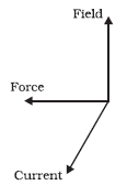
Deflection of current carrying conductor is largest when the direction of current is at the right angles to the direction of the magnetic field.
Fleming's Left Hand Rule
When thumb, forefinger and middle finger of left hand are stretched in such as fashion that they are mutually perpendicular to each other, then according to Fleming's left hand rule if the first finger points in the direction of magnetic field and second finger in the direction of current, then the thumb will point in the direction of motion or the force acting on the conductor.
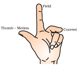
Fleming's left hand rule is mainly applicable in the case of electric generator.
Use of Current Carrying Conductor
Current carrying conductor and magnetic field are used in electric motor, electric generator, loudspeakers, microphones and measuring instruments, etc.
Electric Motor
Electric motor is used in many electrical appliances, such as electric fans, refrigerators, hair dryer, mixers, washing machines, etc.
A rotating device which is used to convert electrical energy to mechanical energy is called ELECTRIC MOTOR.
Working Principle of Electric Motor
The electric motor works on the principle of force on a current carrying conductor in a magnetic field. When a rectangular coil is placed in a magnetic field and current flows through it; a force begins to act on the coil which results in rotational movement of the coil. This happens because a current carrying conductor exerts force on a magnet kept in the vicinity of it.
Structure of Electric Motor:
- An electric motor is composed of two main parts, i.e. a rectangular coil which is placed between the two poles of a magnet.
- The coil ABCD; as shown in the figure; is made of insulated copper wire. It is placed in a way that the arms AB and CD are in perpendicular direction to the direction of magnetic field.
- The ends of the coil are connected to two halves of a split ring. The two halves of the split ring are shown by P and Q in this diagram.
- The split ring is fitted on an axle and there is an insulator layer in between.
- Two static brushes X and Y touch the different halves of the split ring. These brushes are connected to the electricity supply.
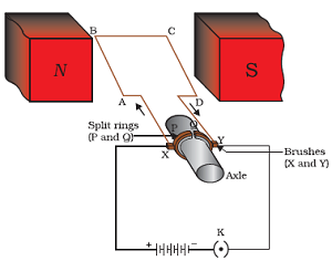
Working of Electric Motor:
- The electric current from power supply comes to the coil through the brush X and returns to the power supply through the brush Y. Thus, the flow of current in arms AB and CD of the coil are in opposite directions to each other.
- When the current flows through the arms of the coil; Fleming’s Left Hand Rule works in this case. Applying the Fleming's Left Hand Rule; when the current and magnetic field are in mutually perpendicular directions, the coil AB moves downwards.
- On the other hand, the coil CD moves upwards because of the same effect. It results in coil; along with the axle; moving in anti-clockwise direction.
- After half rotation, the direction of the coil gets reversed and as a result, the half ring Q meets the brush X and the half ring P meets the brush Y. Now the current moves through the coil CDBA. This would lead to a reverse rotation of the coil and axle.
- To prevent this and to attain a continuous rotational motion of the axle; the split ring acts as a commutator. It reverses the direction of the current through the coil after every half turn. Due to this, the arm AB of the coil which was earlier pushed down is now pushed up. This leads to a continuous rotation of coil in one direction only.
The typical commercial motor has following features:
- Instead of a permanent magnet, commercial motor is composed of an electromagnet. Use of electromagnet ensures a stronger magnetic field.
- There is large number of turns in the conducting coils. Large number of turns in conducting coil produces strong magnetic field, because magnetic produced by current carrying conductor is n-times as large as that produced by single turn.
- A soft iron core is used on which the coil is wound. The soft iron core and the coil wound around it make the armature of the motor. It helps in producing more power from the motor.