Electricity - Class 10th Science
Electric Potential and Potential Difference
Energy acquired by an object because of its position is called potential energy.
Example:
Water flows from a height to lower level because water at height acquires some of energy, which is called potential energy.
If there were no difference in height, water will not flow.
Similarly, when a stone is dropped from a height, it reaches to the ground. This happens because of height, stone acquires some energy, which is called potential energy.
Similarly, when some work is done in the electrical field to move a charge to a reference point from other point, say from infinity, the work done over the charge is stored as energy.
Since, this work is done in the electrical field, thus, energy is known as Electric Potential Energy or ELECTRIC POTENTIAL.
Electric Potential Difference
Electric potential difference between two points in an electric circuit carrying some current as work done to move a unit charge from one point to other.
In other words, if the electric potential at any point, say point A, is greater than at a point B, then electric current flows from point A to B.

Because of electric potential difference between two points, electric current flows in order to maintain equilibrium between two points.
Thus, the potential difference is the electric potential difference between two points. Since, to maintain equilibrium because of potential difference some work is done which is the cause of flow of electric current, thus, potential difference can be defined as the work done in moving of unit electric charge from one point to another point.
Thus, electric potential can be defined as the work done in moving of unit electric charge from one point to another point.
Or, work done in moving unit electric charge between two reference points is called potential difference.
Therefore, Potential Difference = Work done/Charge

Where, V = Potential difference
W is the work done and
Q is the charge or electric charge.
By knowing two among V, W and Q are known, then third one can be calculated using expression in equation (i).
Unit of Electric Potential
The SI unit of electric potential is volt. Volt is denoted by Roman letter 'V'. The unit of electric potential was named in the honour of Italian Scientist Alessandro Volta.
The unit of potential difference is volt (V),
The unit of work done is joule (J) and
The unit of charge 'Q' is coulomb (C)
Therefore, SI unit of V

If 1 joule of work is done to move an electric charge of 1 coulomb, then
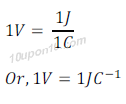
This means 1V of potential difference is the 1 joule of work done to move the electric charge of 1 coulomb.
Voltmeter
Voltmeter is an apparatus, using which potential difference is measured. Voltmeter gives the reading of potential difference in electric circuit by the deflection of needle.
Voltmeter is connected in parallel in an electric circuit.
Measurement of potential difference
Potential difference is measured by a device called voltmetre.
Electric Circuit
Diagram, which shows the whole path of complete movement of electric current, is called ELECTRIC CIRCUIT.
In other words, the close path of electric current is called electric circuit.
Electric circuit will not complete if there is any breaks in the path of electric current. In the condition of break of electric current or electric circuit, electric appliances connect will not work.
Electric Switch
Electric switch is a type of tool which is used to break an electric circuit as per requirement.
In households electric switches are meant to on or off an electrical appliance. For example: when electric switch for fan is put on, fan starts working and when switch is put off electric fan stops working.
This means in the condition of switch on, electric circuit completes and fan or other electrical appliance starts working and in the case of switch is put off, electric circuit breaks and electric appliance does not work or stops working due non-completion of electric circuit.
Circuit Diagram
Pictorial depiction of electric circuit is called CIRCUIT DIAGRAM or electrical circuit diagram.
Symbols used in circuit diagram
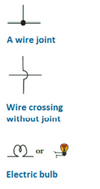
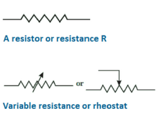
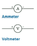
Many components are attached in an electric circuit as per requirement, such as electric bulb, switch, ammeter, voltmeter, etc. These components are shown using symbol in an electric circuit diagram. Some of the symbols given here, which are used in a circuit diagram to show different electrical components.
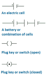
Single electric cell: Two parallel lines one is shorter and thicker than other connected with two horizontal lines at their sides is used to show a single electric cell. Shorter line denotes the negative pole and longer line denotes the positive pole.
A battery or a combination of cells: More than two parallel lines are used to show the combination of cells or a battery. The combination of electric cells is known as battery.
Plug key or Switch (open): Symbol of small brackets with two horizontal lines of their both sides is used to show plug key or open switch.
Plug key or Switch (closed): Symbol used for open switch with a thick dot is used to show closed switch.
A wire joint: A line with another perpendicular line with a big dot at the junction is used to show the wire joints.
Wire crossing without joint: A horizontal straight line with a vertical straight line with a semi circle in the middle is used to show the wire crossing without joint.
Electric bulb: A 'M' letter enclosed within a circle with two horizontal small lines both sides or the picture of a bulb is used to show the electric bulb.
Resistance: A zig-jag line is used to show the resistance.
Rheostat or variable resistance: A zig-jag line with an arrow over it is used to show the variable resistance or rheostat in the electric circuit.
Ammeter: A letter 'A' enclosed in the circle with two horizontal lines is used to show the ammeter.
Voltmeter: A letter 'V' enclosed in a circle with two horizontal lines is used to show the voltmeter.
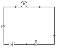
Example of Circuit Diagram:
A simple circuit diagram can be shown as follows:
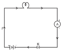
A simple circuit diagram with ammeter can be shown as follows:
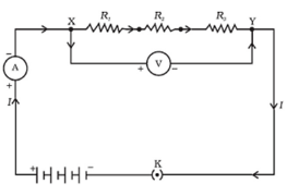
A simple circuit diagram with voltmeter, ammeter and three resistance is shown in figure.
